


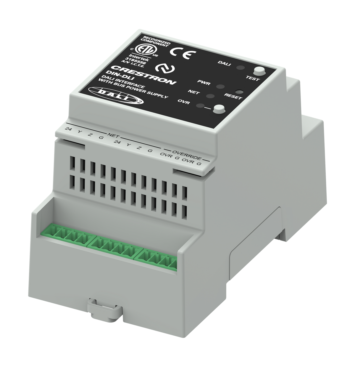
The DIN-DLI is a DALI-2™ certified DALI® interface for Crestron control systems that provides control of one DALI loop.
Overview
The DIN-DLI is a DALI-2™ certified DALI® interface for Crestron control systems that provides control of one DALI loop. Housed in a 3M DIN-rail enclosure, the compact DIN-DLI is capable of controlling DT0, DT1, DT2, DT3, DT4, DT5, DT6, DT7, and DT8 Tc DALI devices. Crestron control system connection is provided through a Cresnet® wired2 or Ethernet with PoE connection. DALI devices can be commissioned through an intuitive web user interface. The DIN-DLI also offers unique features that improve the flexibility and performance of DALI® systems to help with your DALI installation.
One DALI Loop
The single DALI loop on the DIN‑DLI enables control of up to 64 individual DALI devices. With DALI's device level control, lighting loads powered from the same feed can be controlled individually. DALI allows layout changes without new circuit wiring, providing flexibility by allowing zone reconfiguration after a system is installed.
Integrated DALI Power Supply
The design of the DIN‑DLI eliminates the need for external power supplies required by other DALI controllers on the market. Power1 is delivered via PoE or Cresnet, creating a true single-wire installation. Both Cresnet and PoE are capable of powering the communications of all 64 connected DALI devices.
Scene Approximation
This feature eliminates the color temperature popcorn effect when simultaneously controlling a large number of fixtures or groups. Scene Approximation for color control uses scene recall on DALI DT8 Tc drivers to recall color temperature instead of the slower DT8 commands. 16 scenes are evenly spaced across the full range of the lowest common minimum to the highest common maximum color temperature. When color temperature is adjusted, the DIN-DLI recalls the closest scene.
Override Input
Override input is provided to allow an external contact closure to momentarily override the control system program and set each channel output to its override preset level. Factory default override values on DALI devices can be adjusted through the DIN-DLI web user interface.
DIN Rail Installation
The 3M 2.08 in. (52.83 mm) wide DIN‑DLI snaps onto a standard DIN rail for installation in a wall mount enclosure. When installed in an enclosure utilizing 45 mm cutouts, the front panel stays accessible while the connections are concealed.
Module to Module Connectors
Module to Module connectors quickly connect Cresnet and Override between modules without the need for additional wiring or tools.
Cresnet and PoE
The DIN‑DLI communicates with Crestron Home over Ethernet. Other Crestron control systems can make use of the Cresnet control network or Ethernet. A pair of Cresnet ports and module to module connectors allow for easy daisy-chaining of several DIN Rail Series automation control modules. An RJ45 connector enables both data and power to be transmitted to the unit using a single CAT5 or higher cable.
NOTE: The DIN‑DLI is not compatible with Crestron 2‑Series control systems or earlier.


Features
Key Features
- Interfaces with one independent DALI® loop
- DALI-2™ certified
- Supports DT0, DT1, DT2, DT3, DT4, DT5, DT6, DT7, and DT8 Tc DALI Devices
- Controls up to 64 DALI devices
- Provides DALI loop power1 for communication
- Power using Cresnet network or PoE for single-wire installation
- Communicates with the Crestron Home® OS over Ethernet
- Commissioned through Web UI for easy setup
- Fast color temperature control through Scene Approximation
- Override input
- Link-local direct connection to a PC for commissioning when powered via Cresnet
- 3M wide DIN rail mounting
- Works with the Crestron Home® OS
- Test wiring and perform driver replacement without a computer
Specifications
| Power | |
| Cresnet Power Usage | 6W (250mA @ 24V) |
| PoE Power Usage | IEEE 802.3af (802.3at Type 1) Class 2 PoE Powered Device (6.5W) |
| Load Ratings | |
| DALI Loop | 1 |
| DALI Devices | 64 |
| Load Types | DALI devices DT0, DT1, DT2, DT3, DT4, DT5, DT6, DT7, and DT8 Tc |
| DALI Loop Power Supply | |
| DALI Loop | Maximum: 0.25A |
| Power Supply1 | Continuous: 0.17A |
| Communications | |
| Cresnet | Cresnet secondary mode |
| Ethernet |
100BASE-TX; |
| DALI | One DALI loop; DALI-2™ Certified; Provides power1 and communication for the DALI loop; Up 64 DALI drivers in up to 16 DALI groups; DT0, DT1, DT2, DT3, DT4, DT5, DT6, DT7 and DT8 Tc support |
| Connectors | |
| Module to Module | (2) Module to module connectors; Provides Cresnet and Override to connected modules |
| NET | (2) 4-pin 3.5 mm detachable terminal blocks, paralleled; Cresnet® secondary port |
| OVERRIDE | (2) 2-pin 3.5 mm detachable terminal blocks, paralleled; Sensing input for external low-voltage contact closure; Activates override mode when a closure is present; Minimum contact closure rating: 10mA (per module) at 24V |
| LAN PoE | (1) 8-pin RJ-45, female; 100BASE-TX Ethernet port; Green and yellow LEDs indicate Ethernet port status; Cresnet network power disables PoE power; Link-local direct connection to a PC for commissioning when powered via Cresnet |
| DA+ / DA- | (2) 2-pin 3.5 mm spring terminals, paralleled; Control a single DALI loop; A DALI loop controls up to 64 drivers; 3kVAC isolation from Cresnet (NET) and Ethernet (LAN PoE) ports; Wire Gauge: 12-24 AWG solid wire or 14-24 AWG stranded wire |
| Controls and Indicators | |
| OVR | (1) Red LED and (1) push button; For enabling override mode |
| PWR | (1) Green LED; Indicates power to device |
| NET | (1) Yellow LED; Indicates communication with the control processor |
| RESET | (1) Recessed miniature push button; Resets internal processor on momentary push; Hold for ten seconds to perform a factory restore |
| DALI | (1) Yellow LED; LED lights to indicate DALI power, communication, and error |
| TEST | (1) Push button; Provides local control of the lights on momentary push; Hold to initiate a single device replacement |
| Environmental | |
| Local In-cabinet Air Temperature | 32° to 122 °F (0° to 50°C) |
| Humidity | 10% to 90% RH (noncondensing) |
| Heat Dissipation | 13.6 BTU/hr |
| Construction | |
| Enclosure | Light gray polycarbonate housing with polycarbonate label overlay |
| Mounting | 35 mm DIN EN 60715 rail mount, DIN 43880 form factor for enclosures with 45 mm front panel cutout, occupies 3 DIN module spaces (54 mm) |
| Dimensions | |
| Height | 3.68 in. (93.70 mm) |
| Width | 2.08 in. (52.83 mm) |
| Depth | 2.32 in. (59 mm) |
| Weight | |
| 0.24 lb (113.3 g) | |
| Compliance | |
|
Regulatory Model: M202236001 Intertek® Recognized for US & Canada, CE, FCC Class B, IC, WEEE |
|

- Our primary carrier of choice is UPS, however, occasionally orders are shipped via FedEx and USPS.
- All in-stock orders will be shipped Standard Ground with a 3-5 business day delivery time frame.
- Dropship orders may require longer processing times with our manufacturers.
- Deputy Electronics will not ship to PO boxes. A representative will contact you should you enter an unacceptable shipping address. Your order will not be processed until an updated shipping address is provided. If no address is provided within 30 days of the order date, your order will be canceled.
- All orders shipping within the 48 contiguous states will be charged a standard $9.99 shipping and handling fee.
- Should you need your order expedited, please contact a customer service representative at (812) 522-8070 Monday – Friday from 8:00 am to 5:00 pm for pricing/rate quotes. Please be advised that not all items will qualify for expedited shipping.
- Orders placed on Friday after business hours, Saturday, Sunday, or Holidays will not qualify for special shipping methods such as Next Day Air, Overnight Shipping, Second Day Air, or 3 Day Select.
- Expedited orders are only able to ship on business days.
